


4 Channel NAC Panel Module
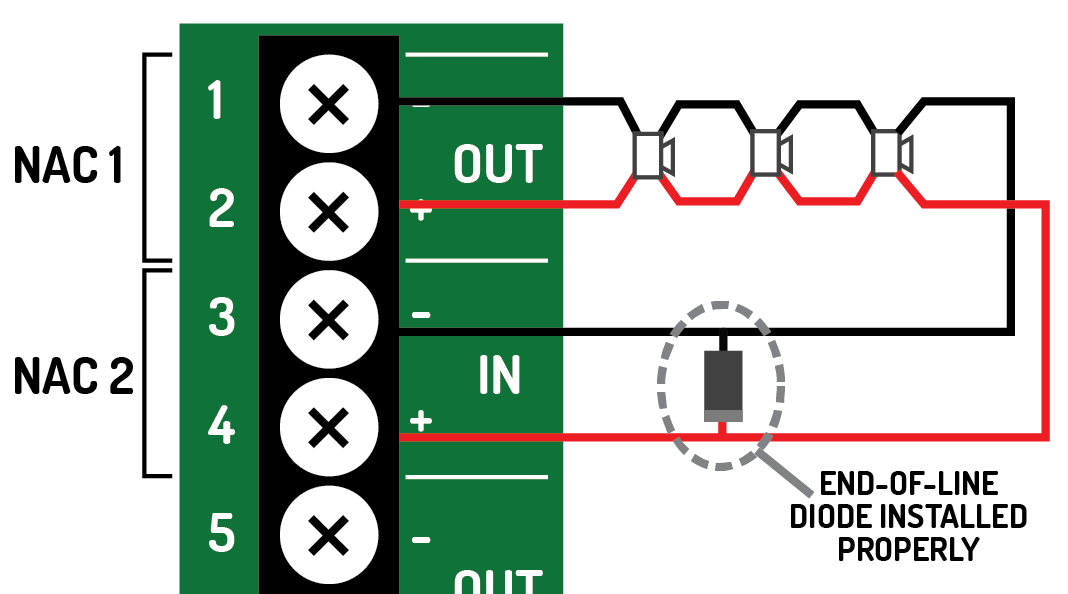
Install the End-of-Line Diode in the proper orientation.
INCORRECT ORIENTATION

CORRECT ORIENTATION
INCORRECT ORIENTATION
CORRECT ORIENTATION
Investigate the wiring problem and correct any interruptions in the circuit. When the wiring issue is resolved, the trouble on the panel will restore.
Recalculate the load on the system and remove the number of devices necessary to ensure the circuit's current limit is not exceeded. To test the current limit, activate the NAC circuits and verify proper operation. If panel posts a Current Limit Trouble, refer to NAC Current Limit Trouble below.
Investigate the wiring, looking for an obvious cause of a short circuit. If not obvious cause exists, perform the following procedure.
- Disconnect the field wiring from the panel (both ends of a Class A circuit). The trouble should change to an Open Circuit Trouble.
- Break the connection at the halfway point of the wiring pathway.
- Using an ohm meter, determine which half of the path contains the short.
- Repeat steps 2 and 3 until the short is located.
- Repair the cause of the short, reconnect all of the breaks, and reconnect the field wiring to the panel.
If the wiring path is excessively long, a lower gauge wire may need to be used. Use the calculator in to verify that the appropriate wire was used during installation.
If the appropriate wire was used, there may a high resistance connection somewhere on the circuit.
- To locate the cause, disconnect the field wiring from the IN terminals.
- Activate the circuit.
- Determine whether the last device on the circuit is still operational. If not, locate the last operational device along the path. The voltage drop is likely between the operational and non-operational device. Move to step 6.
- If all devices are operational, measure the voltage at the OUT terminal and the IN terminal for comparison.
- Starting from the OUT terminal, measure the circuit voltage at various locations until a significant voltage drop is located.
- Repair the loose connection between these two devices. If no loose connections are found, temporarily run new wire between the two devices and determine if this corrects the trouble. If this corrects the issue, permanently replace the wire between the two devices.
Correct the programming so that it matches the wiring configuration.
Verify the programmed current limit. If the limit is set correctly, verify that the installed devices do not exceed the programmed current limit. Then, check for defective devices on the circuit.
8 Channel Conventional Zone Panel Module
Investigate the wiring problem and correct any interruptions in the circuit. When the wiring issue is resolved, the trouble on the panel will restore.
Investigate the wiring, looking for an obvious cause of a short circuit. If no obvious cause exists, perform the following procedure.
- Disconnect the field wiring from the panel (both ends of a Class A circuit). The trouble should change to an Open Circuit Trouble.
- Break the connection at the halfway point of the wiring pathway.
- Using an ohm meter, determine which half of the path contains the short.
- Repeat steps 2 and 3 until the short is located.
- Repair the cause of the short, reconnect all of the breaks, and reconnect the field wiring to the panel.
If activations are not intended to be short circuits, add (or correct the wiring of) trigger resistor.
If activations are intended to be short circuits, change Short Circuit Activation field in panel programming to "Yes".
Restore the activation and measure the circuit voltage as directed below.
- If voltage at panel is < 15 V, verify that the board is fully seated in slot. If the board is properly installed, contact Technical Support.
- If the voltage at the panel is > 15V, measure the voltage at the device.If voltage at device is < 15 V, troubleshoot the field wiring.If voltage at device is > 15 V, using an ohm meter, verify the value of the trigger resistor is 470 ohms +/- 20%.
- If voltage at device is > 15 V, using an ohm meter, verify the value of the trigger resistor is 470 ohms +/- 20%.
Check panel programming. Ensure that the appropriate Input Action is selected. Selecting "Transparent" will result in no indication on the panel unless the input is part of a cause and effect relationship.